Gi Pipe Manufacturer In India
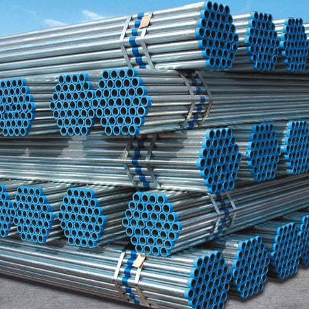
Gi Pipe or galvanizing is the process of applying protective zinc coating to steel or iron to prevent corrosion. The most common method is hot-dip galvanizing, where the parts are immersed in a molten zinc bath.
Gi Pipes Process
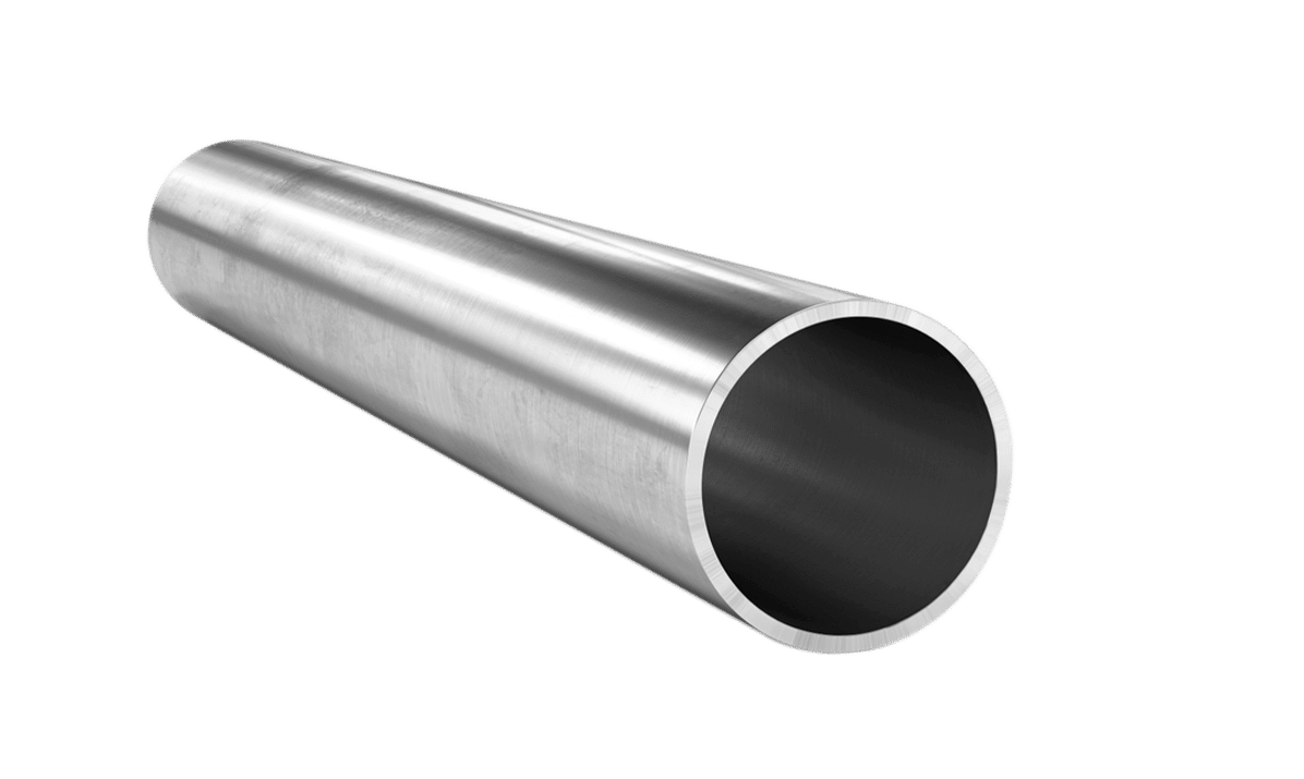
Steel Pipe, coated with a layer of zinc metal, is known as Galvanized steel. During the Gi Pipe process, the steel is immersed in a molten zinc bath to provide a rigid and uniform barrier. Gi pipe and tubes for water supply, structural applications and so on.
Gi pipe are generally used for the distribution of treated or raw water in rural or urban areas. These pipes are cheaper, lightweight and easy to use. The following details refer to IS 1239 Part 1 below. .
Material Supply:
Supply of steel pipes shall comply with IS 1387.
Gi Pipes Chemical composition:
The chemical composition of the steel shall comply with Table 1 in the Pot Sample analysis.
| Carbon | Manganese | Sulphur | Phosphorus |
| (1) | (2) | (3) | (4) |
| 0.20 | 1.30 | 0.040 | 0.040 |
To achieve long-term structural performance in the most demanding weather conditions, designers, builders and consumers have begun to use zinc-coated steel pipes. This is due to the fact that zinc-plated galvanized steel pipes and the pipe withstand wind, water and road salts attacks.
In addition to being easy to pocket, Gi pipe are corrosion resistant, lightweight, easy to use during transport and easy to add.
Welded pipes shall be manufactured from hot rolled steel strip for welded pipes and pipes in accordance with IS 10748 or cold rolled low carbon steel sheets and strips in accordance with IS-513.
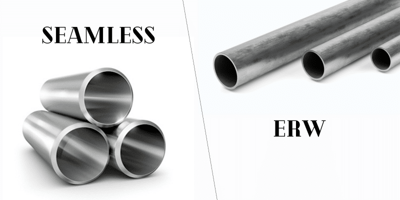
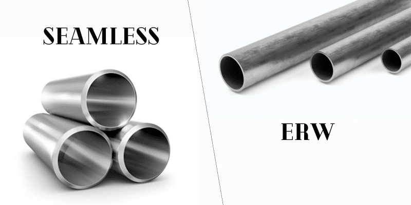
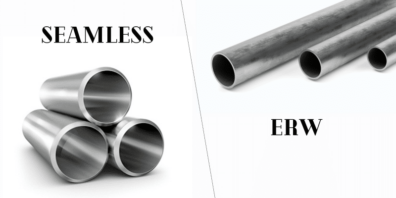
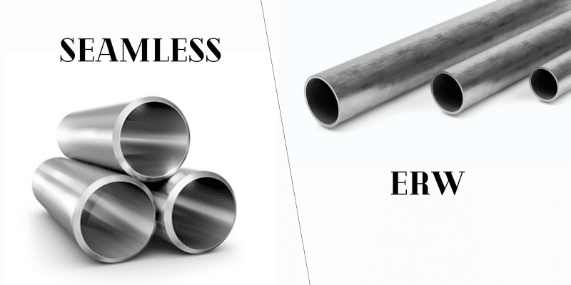
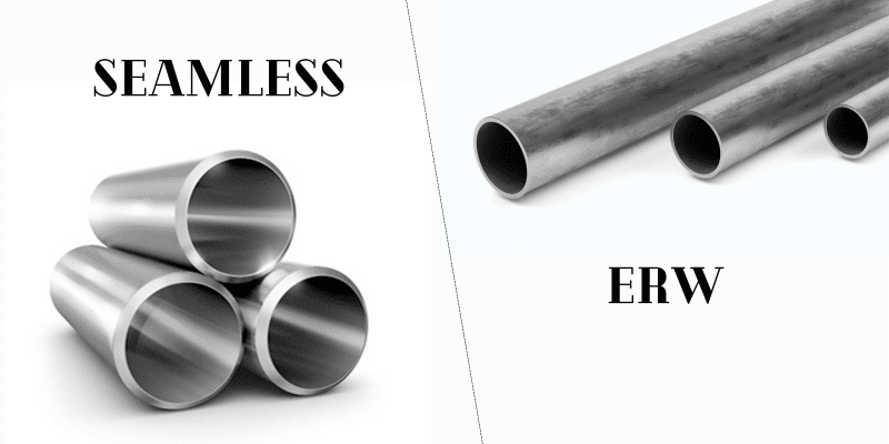
Steel pipes shall be produced by one of the following processes:
Hot finished seamless (HFS)
Cold finished seamless (CDS)
Hot finished welded (HFW)
Electrical resistance welded or high frequency induction welded (ERW or HFIW).
For welded pipes, the height of the inner weld fin shall not exceed 60 percent of the specified wall thickness.
Table 2: Permitted Variation in Product Analysis according to IS 1239 Part 1
| SI.No | Content | variation Over Specified Limit Percent Max |
| (1) | (2) | (3) |
| 1) | Carbon | 0.02 |
| 2) | Manganese | 0.04 |
| 3) | Sulphur | 0.005 |
| 4) | Phosphorus | 0.005 |
Dimensions:
Table 2: Permitted Variation in Product Analysis according to IS 1239 Part 1
| Nominal Bore | Outside Diameter | Thickness | Mass Of Tube | ||
| mm | Maximum mm | Minimum mm | mm | Plain End
Kg/m |
screwed and Socketed
Kg/m |
| 6 | 10.1 | 9.7 | 1.8 | 0.360 | 0.363 |
| 8 | 13.6 | 13.2 | 1.8 | 0.515 | 0.519 |
| 10 | 17.1 | 16.7 | 1.8 | 0.670 | 0.676 |
| 15 | 21.4 | 21.0 | 2.0 | 0.947 | 0.956 |
| 20 | 26.9 | 26.4 | 2.3 | 1.38 | 1.39 |
| 25 | 33.8 | 33.2 | 2.6 | 1.98 | 2.00 |
| 32 | 42.5 | 41.9 | 2.6 | 2.54 | 2.57 |
| 40 | 48.4 | 47.8 | 2.9 | 3.23 | 3.27 |
| 50 | 60.2 | 59.6 | 2.9 | 4.08 | 4.15 |
| 65 | 76.0 | 75.2 | 3.2 | 5.71 | 5.83 |
| 80 | 88.7 | 87.9 | 3.2 | 6.72 | 6.89 |
| 100 | 113.9 | 113.0 | 3.6 | 9.75 | 10.0 |
Table 4 Steel Pipes Dimensions and Nominal Mass – Medium to IS 1239 Part 1
| Nominal Bore | Outside Diameter | Thickness | Mass Of Tube | ||
| mm | Maximum mm | Minimum mm | mm | Plain End
kg/mm |
Screwed And Socketed Kg/m |
| 6 | 10.6 | 9.8 | 2.0 | 0.404 | 0.407 |
| 8 | 14.0 | 13.2 | 2.3 | 0.641 | 0.645 |
| 10 | 17.5 | 16.7 | 2.3 | 0.839 | 0.845 |
| 15 | 21.8 | 21.0 | 2.6 | 1.21 | 1.22 |
| 20 | 27.3 | 26.5 | 2.6 | 1.56 | 1.57 |
| 25 | 34.2 | 33.3 | 3.2 | 2.41 | 2.43 |
| 32 | 42.9 | 42.0 | 3.2 | 3.10 | 3.13 |
| 40 | 48.8 | 47.9 | 3.2 | 3.56 | 3.60 |
| 50 | 60.8 | 59.7 | 3.6 | 5.03 | 5.10 |
| 65 | 76.6 | 75.3 | 3.6 | 6.42 | 6.54 |
| 80 | 89.5 | 88.0 | 4.0 | 8.36 | 8.53 |
| 100 | 115.0 | 113.1 | 4.5 | 12.2 | 12.5 |
| 125 | 140.8 | 138.5 | 4.8 | 15.9 | 16.4 |
| 150 | 166.5 | 163.9 | 4.8 | 18.9 | 19.5 |
Joints:
All screwed pipes must be supplied with pipe threads in accordance with IS 554. The gauge according to IS 8999 should be regarded as an adequate test for the suitability of IS 554 threads.
Galvanized:
When the tubes need to be galvanized, the zinc coating in the tubes must comply with IS 4736.
The Gi pipe to be screwed must be galvanized before screwing.

